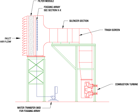
Inlet Fogging
Inlet Cooling Systems (also known as Fogging Systems) augment the power output of a Gas Turbine. With all Stainless Steel materials, AMCO's fogging systems use positive displacement pumps to pump demineralized/ de-ionized water at 3000 psi (207 bar) from the pumping skid to spray nozzle manifolds located in the air duct downstream of the filter housing and ahead of the silencer.
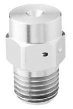
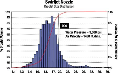
- Swirl Jet Nozzle
- Inlet Fogging Sizing
- Pump Skid
- System Controls
- P&ID, Piping & Instrumentation
- AMCO Field Services & Technical Support
- Higher nozzle flow - fewer nozzles required
- 90% droplets mass is less than 20 microns (see Swirljet Nozzle table)
- Smaller droplets - better evaporation
- Durable design - no impaction pin
- Safety lock wired to the manifold using aircraft industry standard locking methods
- Nozzle adapters are attached to seamless 316L stainless steel tubing via a full penetration TIG weld in accordance with ANSI-B31.1 standards
- Provides increased reliability, less maintenance, and longer service life
Moisture (GPM) required to lower inlet temperature
Data:
Temperature Dry Bulb: 110°F
Temperature Wet Bulb: 70°F
Turbine Air Flow: 745,388 ft3/min
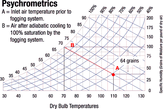
From Table (See Above):
Humidity Ratio: 64 grains/(lb dry air)
Specific Volume: 13.75 ft3/(lb dry air)
Calculation
| (745,388 ft3/min)(64 grains/lb. of dry air) |
= 59.7 GPM 60 GPM |
| (7000 grains/lb. of water)(13.75 ft3/lb. of dry air)(8.3lbs/gallon) |
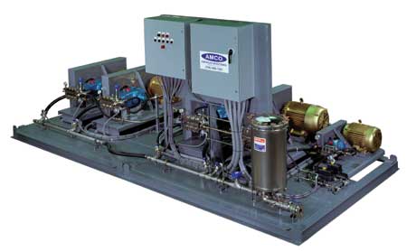
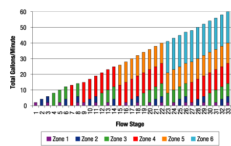
The AMCO direct spray inlet cooling system is the pump and control skid, and inlet nozzle array engineered to meet or exceed the highest industry standards. Referring to the Inlet Side View Drawing, Spray Zone Flow Table, and Cooling Increment Table below as an example, the AMCO skid is providing 60 GPM with 6 cooling zones 32 nozzle lines, allowing 33 separate stages of cooling at increments of 1.3°F. AMCO designs its systems with these small cooling steps in order to prevent shocking the engine, which could warp the casing, and to allow the turbine controls to adjust to the new conditions.
Features
- Heavy duty, premium TEFC electric motors
- Ceramic plunger pumps with stainless steel heads
- High efficiency water filter
- Motor control center
- System control
- Individual zones (pumps) provide for multiple stages, allowing for increments of 1° F
- Engineered to meet or exceed industry standards
- All piping and welding to ANSI B31.1 standards
- All 316L stainless steel construction
Spray Zone Flow Table
Nozzle Array
Cooling Increment Table
| Zone Flow at 110° F Twb | |||||
| 40° F Cooling | |||||
| Zone | Lines | Nozzle | % Flow | GPM | Cooling |
| 1 | 1 | 29 | 3.3% | 2 | 1.3°F |
| 2 | 2 | 58 | 6.6% | 4 | 2.6°F |
| 3 | 4 | 114 | 13.3% | 8 | 5.3°F |
| 4 | 7 | 186 | 21.7% | 13 | 8.7°F |
| 5 | 7 | 186 | 21.7% | 13 | 8.7°F |
| 6 | 11 | 286 | 33.4% | 20 | 13.4°F |
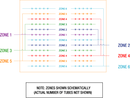
Inlet Side View
Control of the inlet coolers can be accomplished with one of three methods.
- Personal computer
- Programmable logic controller (PLC)
- Direct programming into a plant digital control system (DCS)
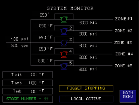
A typical AMCO control system delivers precise cooling control with typical increments of 1°F with PLC logic managing multiple cooling zones.
Each zone consists of one or more nozzle manifold lines being opened. Optimum cooling is achieved with an algorithm that selects the needed flow stage of one or more zones.
The Control Panel View and Operator Interface Screens pictured below represent (2) of many screens available on the user-friendly operator interface panels to monitor system performance and perform system diagnostics.
Features
- Advanced PLC logic manages multiple cooling zones
- Typical cooling increments of 1°F
- Prevents shocking the gas turbine
- Prevents warping the casing
- Allows the gas turbines controls to adjust
- Maximum versatility to meet all inlet conditions
- Complete instrumentation to monitor system operation and provide alarms and data feedback
Control Panel View
Operator Interface Screen
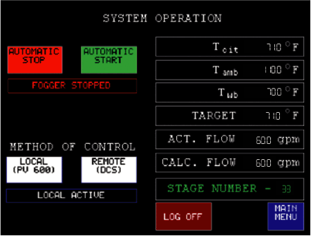
Please click for a larger picture
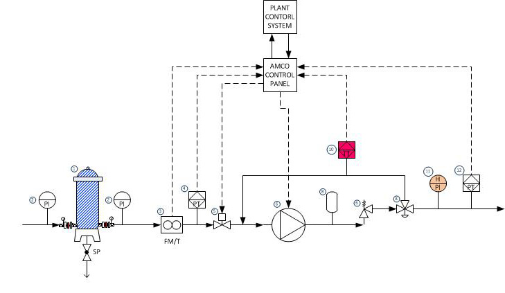
| No. | Description |
| 1 | Filter |
| 2 | Low-Pressure Gauge |
| 3 | Flow Meter/Transmitter |
| 4 | Low-Pressure Transmitter |
| 5 | Low-Pressure Solenoid Valve |
| 6 | Pressure Relief Valve |
| 7 | High-Pressure Pump |
| 8 | Pulsation Dampener |
| 9 | Pressure Control Valve |
| 10 | Temperature Transmitter |
| 11 | High-Pressure Gauge |
| 12 | High-Pressure Transmitter |
AMCO Field Service Engineers and Technicians are available for support on request. Available services include installation supervision, start-up & commissioning, and routine maintenance. Yearly service contracts are available on request as well.
AMCO
10402 Rodney Street
Pineville, NC, USA 28134
Phone: (704) 889-7281
Fax: (704) 8897270
Divisions: Commercial & Industrial Humidification Control Systems Division|Water Treatment Division
Gas Turbine Cooling Division|Control Panel Division

Proudly manufactured in the USA for over 100 years.